Radio
- - - - - - - - - - - - - - - - - - - - - - - - - - - - - - - - - -
In 2020, I attained an amateur radio station license (callsign, KO4DNM) and soon after, upgraded to the General class license. In this time, I found myself deeply interested in antenna design and construction, and constructed a number of antennas, each resonant at the different amateur radio station frequency bands. These frequency ranges lie within the HF spectrum, between 1.8Mhz and 29Mhz. I focused largely on the ~14MHz region (20M Band) during the day time, and lower frequencies at night (~7MHz, the 40M Band, was one of my favorites). Propagation was often nicely split in this manner, with optimal long-distance contact best on the higher frequencies during the light hours, with a sometimes-sudden shift to optimal performance on the lower frequencies as the sun set. During this time, I made over 700 logged radio contacts, including at least one person from each continent, and nearly 100 different countries. More info on this can be found on my QRZ and HRDLog profiles. To produce these results, I had to create a robust plan including details as simple as how many feet of coaxial cable I would need to cut, to much more complicated design of the antennas themselves. My plan included some of the following elements:
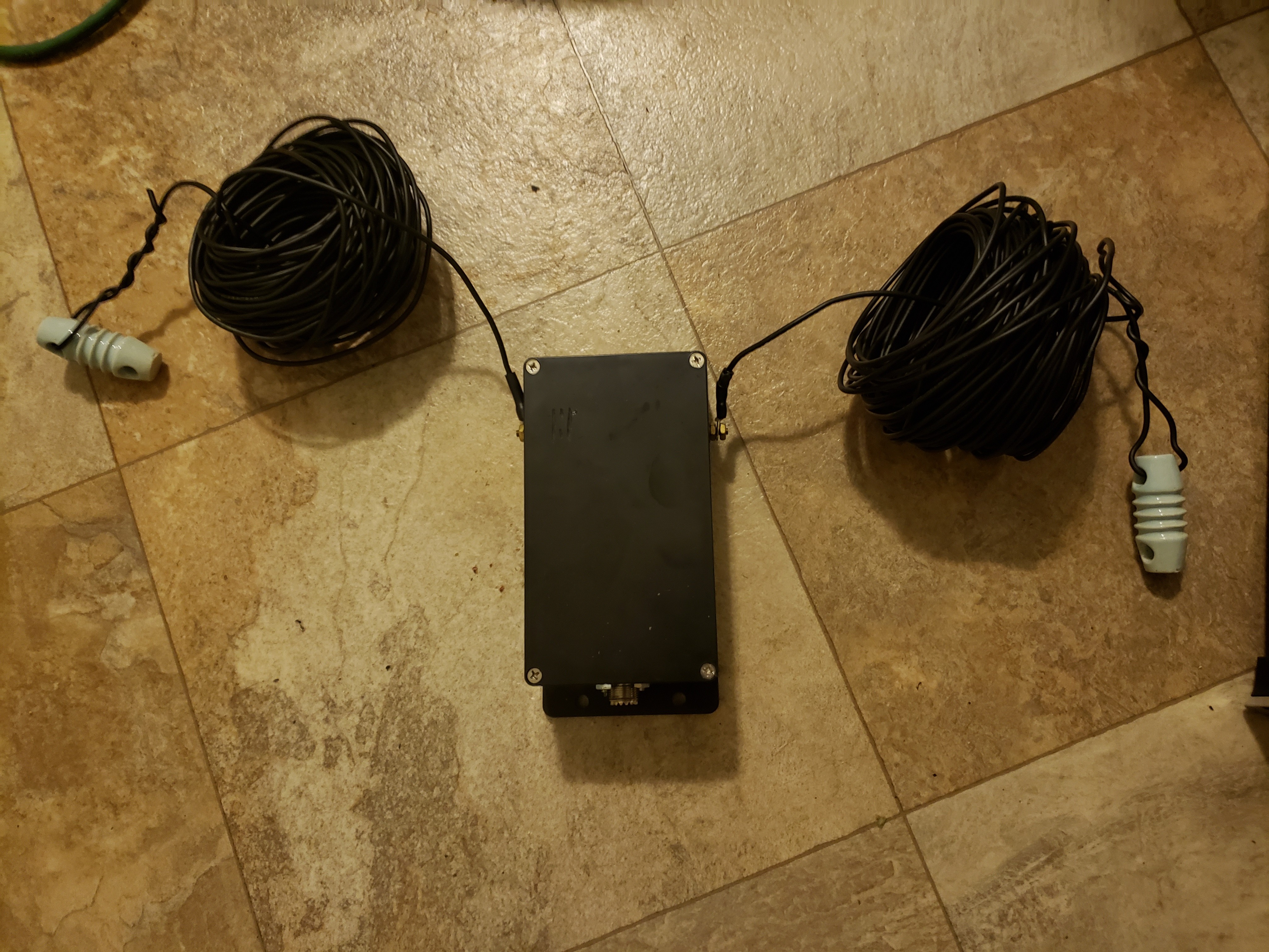
Step 1: Location Planning: Determine optimal location for antennas as well as optimal antenna type; I settled on a multi-element dipole (also called a "fan dipole" for the lower frequencies, and a hex-beam antenna for the higher frequencies)
Step 2: Antenna Design: Complete antenna design (using MMANA-GAL)
Step 3: Feed Line: Determine sufficient quantity of coax, as well as high quality RF connectors
Step 4: Logistics: Acquire necessary materials for antenna (copper wire for antenna elements, proper-type toroidal cores for baluns)
Step 5: Construction of the antennas, Phase I: Wire Elements: For the dipole, this meant measuring out the elements to their resonant lengths, while also taking into account an increase in velocity due to the rubber coating, which resulted in lowering of the resonant frequency by a small, but significant degree. For the hexbeam antenna, I ultimately ended up purchasing a used frame in which I cut new wire elements for.
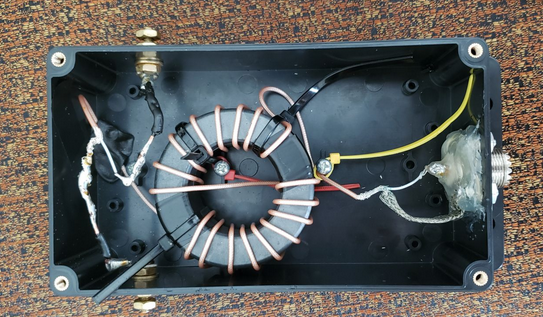
Step 6: Construction, Phase II: Baluns / Chokes: Due to the imperfect feed-point impedance of antennas in the real world, especially a wire dipole used on a wide range of frequencies, I decided to implement a balun for the dipole antenna, and a common mode choke (or 1:1 balun) for the hexbeam (as the hexbeam is configured to be resonant at all desired frequencies)
Step 7: Verification: At this point, everything was built and ready for implementation, and I double-checked all element lengths as well as any connections I made when constructing the balun and isntalling the PL-259 RF connectors on the RF400 coax.
Step 8: Implementation: I decided to implement the antennas in "stages", and installed the hexbeam antenna first. After a few weeks, the dipole was also installed.
Step 9: Testing: After installing the antennas, I performed a wide array of different tests to ensure that I was achieving optimal power transfer between the 100w output of my HF radio and the antenna elements. One of my favorite methods of testing antennas and RF circuits in general is with a VNA, and thanks to the open-source NanoVNA, I, as an independent entity can afford an instrument like a VNA which would otherwise cost upwards of $3000. I also performed SWR tests, as well as TDR tests. I was able to acquire a used Tektronix TDR analyzer, which is great for analyzing feed lines for any shorts, opens, or other issues.
Step 10: The last step of the plan, which is to use and enjoy the antennas. These two antennas have been used to achieve communications, both voice and digital protocols, with people in nearly 100 countries and every continent, including Australia, New Zealand, Japan, and many more. I have experimented with a large number of different communications protocols ranging from:
Single side-band(SSB): USB/LSB
Phase shift keying (PSK): PSK-31
Digital voice: FreeDV
Multiple frequency-shift keying (MFSK): OLIVIA, JT65, FT4, FT8 (two of various incredible weak-signal mode created by astrophysicist Joe Taylor (K1JT)
Frequency shift keying (FSK): RTTY (Radio teletype)
Hellschreiber
- - - - - - - - - - - - - - - - - - - - - - - - - - - - - - - - - -
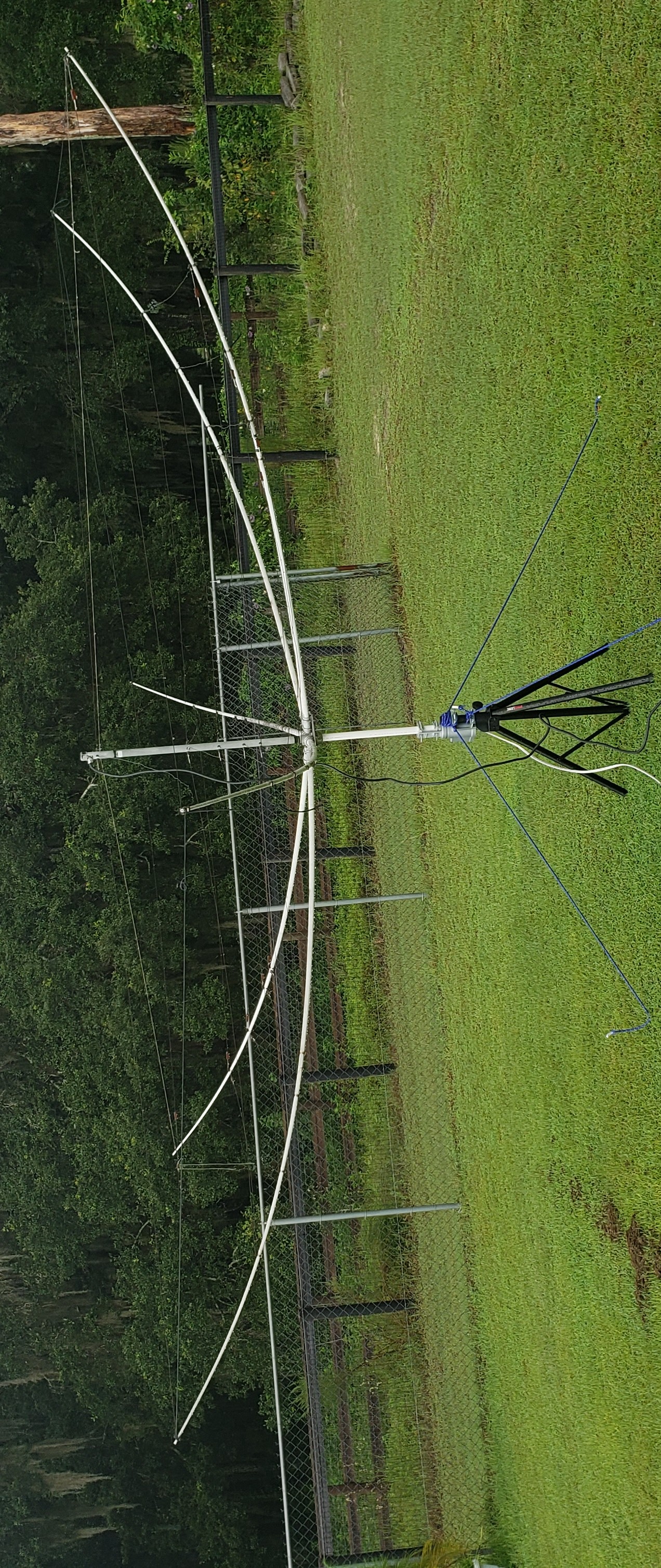
Above: 6-Band hexbeam antenna that I also installed. In order to take advantage of directional effects, I mounted this antenna on a tripod, connected to a TV antenna rotator which I routed underground and then through my window using a custom-built pass-through with PL-259 connections