uSDX: Open Source HF Radio
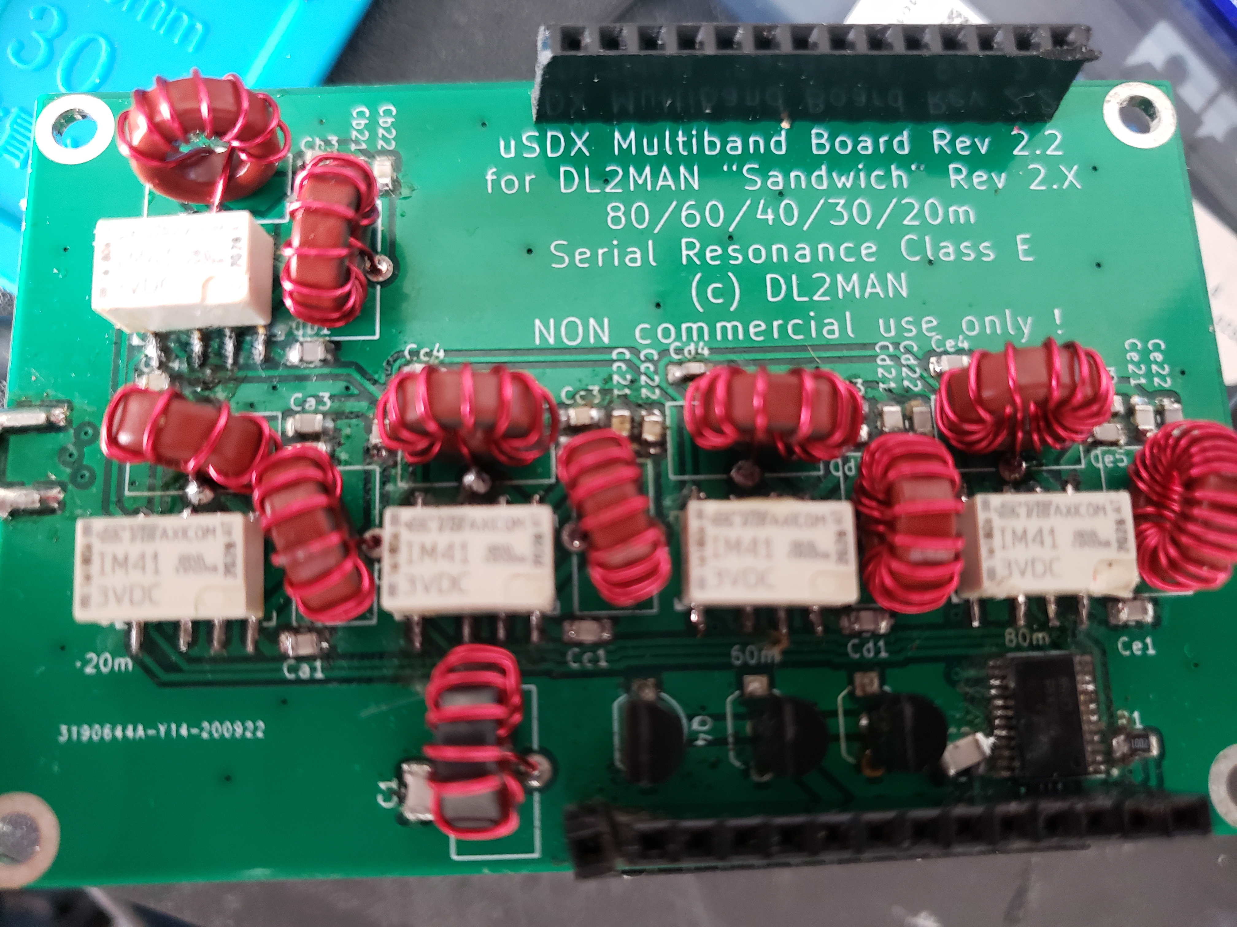
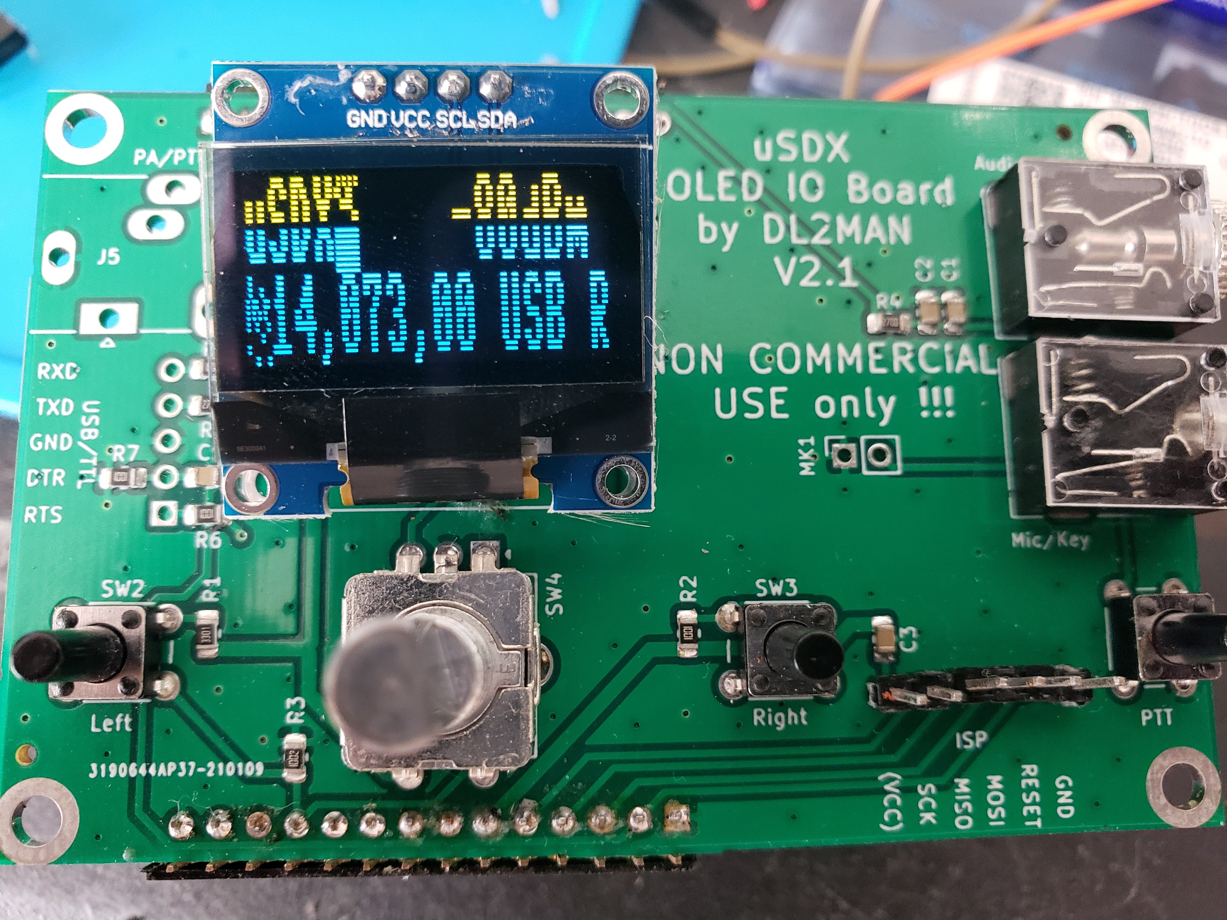
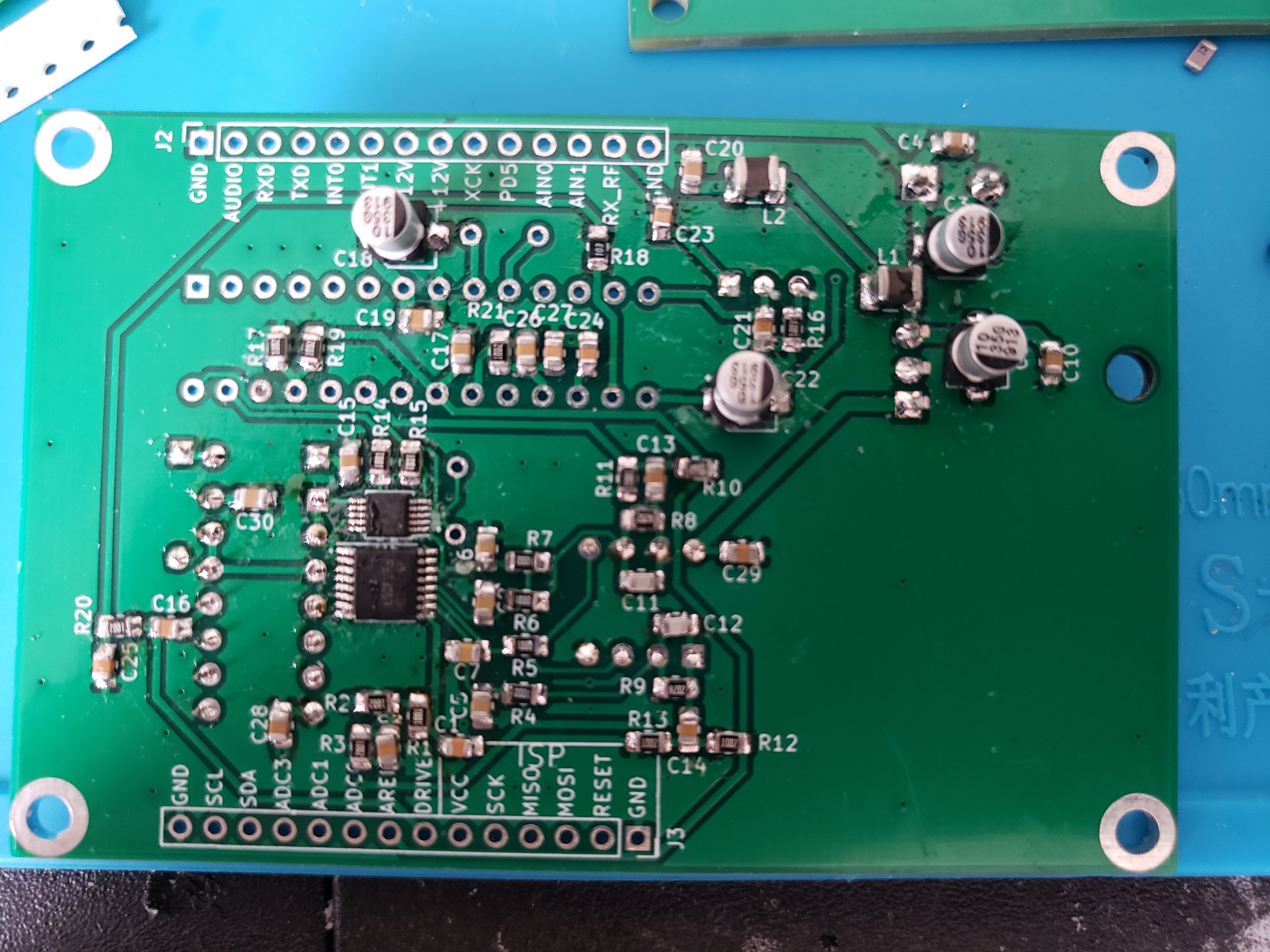
Pictured: The uSDX, a credit card-sized fully operational HF radio capable of modulating SSB (USB and LSB), as well as CW. There are multiple versions of this project. This one was created by Manuel, DL2MAN, and the software originally by Guide, PE1NNZ. I also built one of the other original versions by Barb, WB2CBA. This is one of my favorite open source projects to date, as the community was quite small and I was able to help, as well as be helped, by others. A lot of knowledge and experience was shared. Specifically, a problem arose where a number of people were receiving ATMETA328P microcontrollers without bootloaders. I made a guide for them to succesfully load the bootloader onto their microcontroller via the command prompt, using a breadboard and USB-ASP. This then allowed them to upload the uSDX firmware via their Arduino's.
This project consisted of many parts, and was a great learning experience. The RF filter board was especially interesting, as it was my first introduction into Class E amplifiers and serial resonance. This made it quite a challenge, but was extremely rewarding, as the values for each frequency band had to be optimized while maintaining that optimization for all. I did this using a VNA and LC Meter. The board was designed by Manuel, DL2MAN, to allow for five frequency bands, and each pair of toroids had to be tuned to the correct frequency band, which was done by changing the number of times the magnet wire was wrapped around the toroid, as well as the capacitor values. If you're interested in learning more about the uSDX, the groups.io page is a great place to start.
Hardware Repair: DJI Phantom Drone
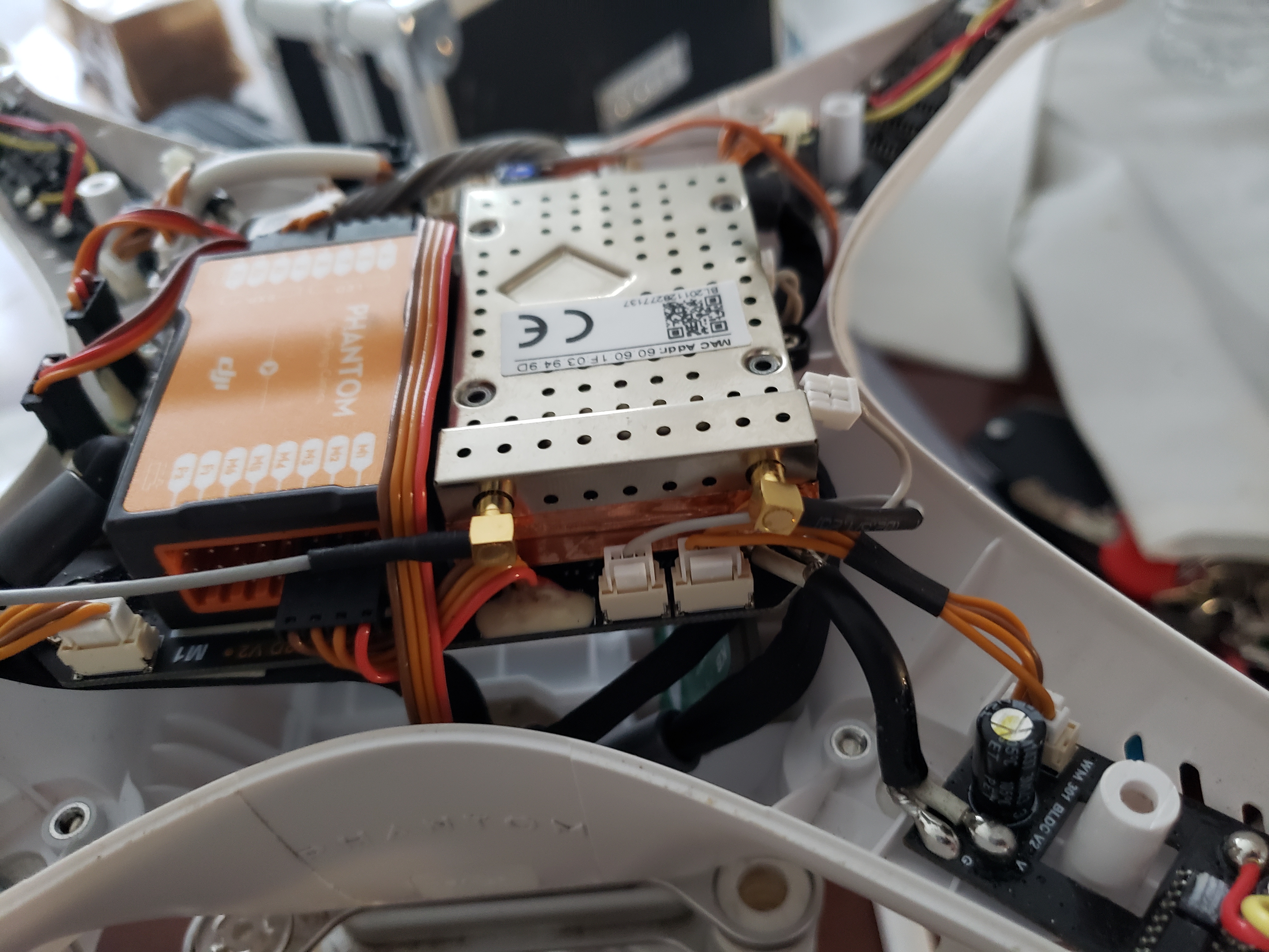
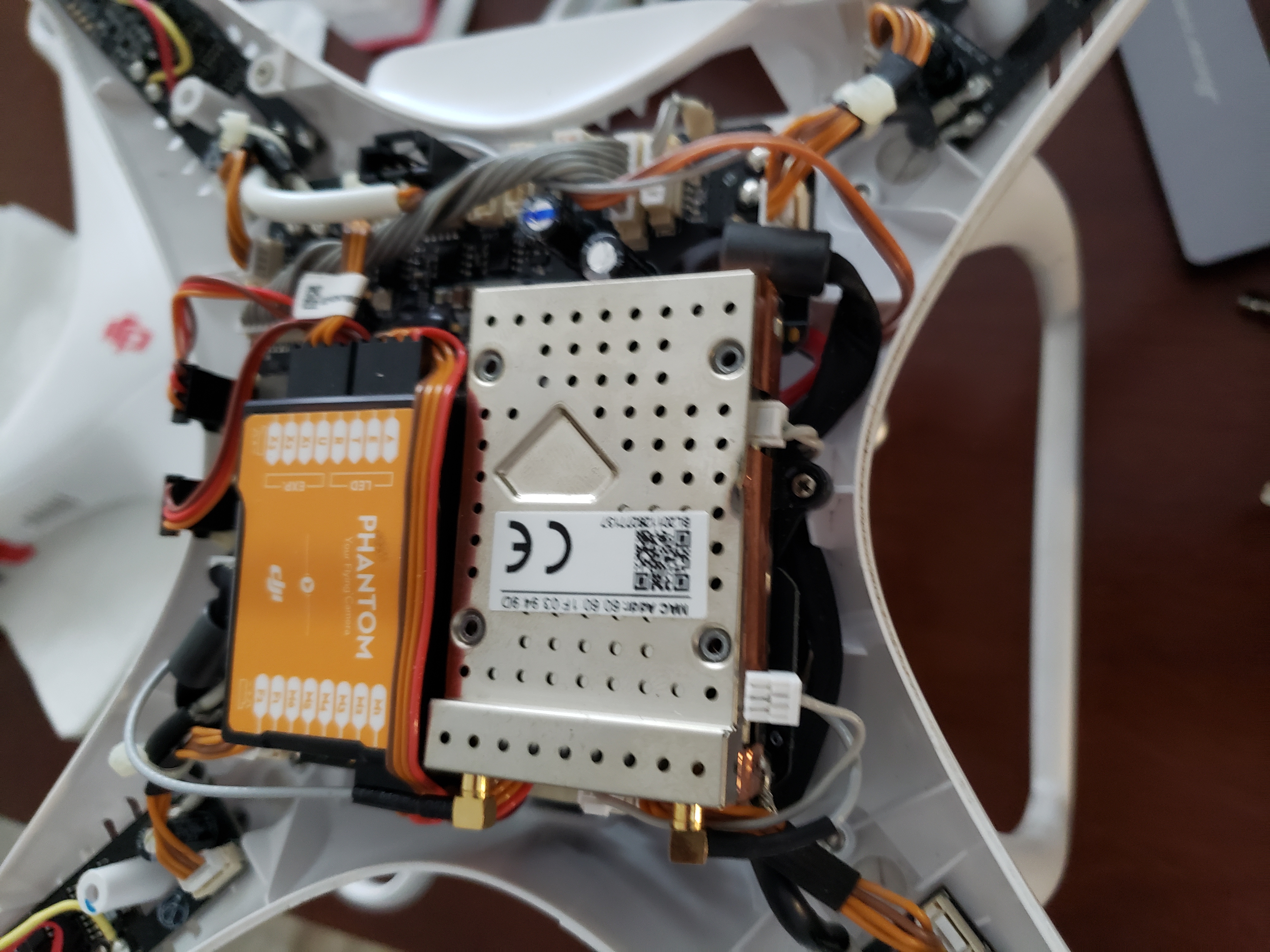
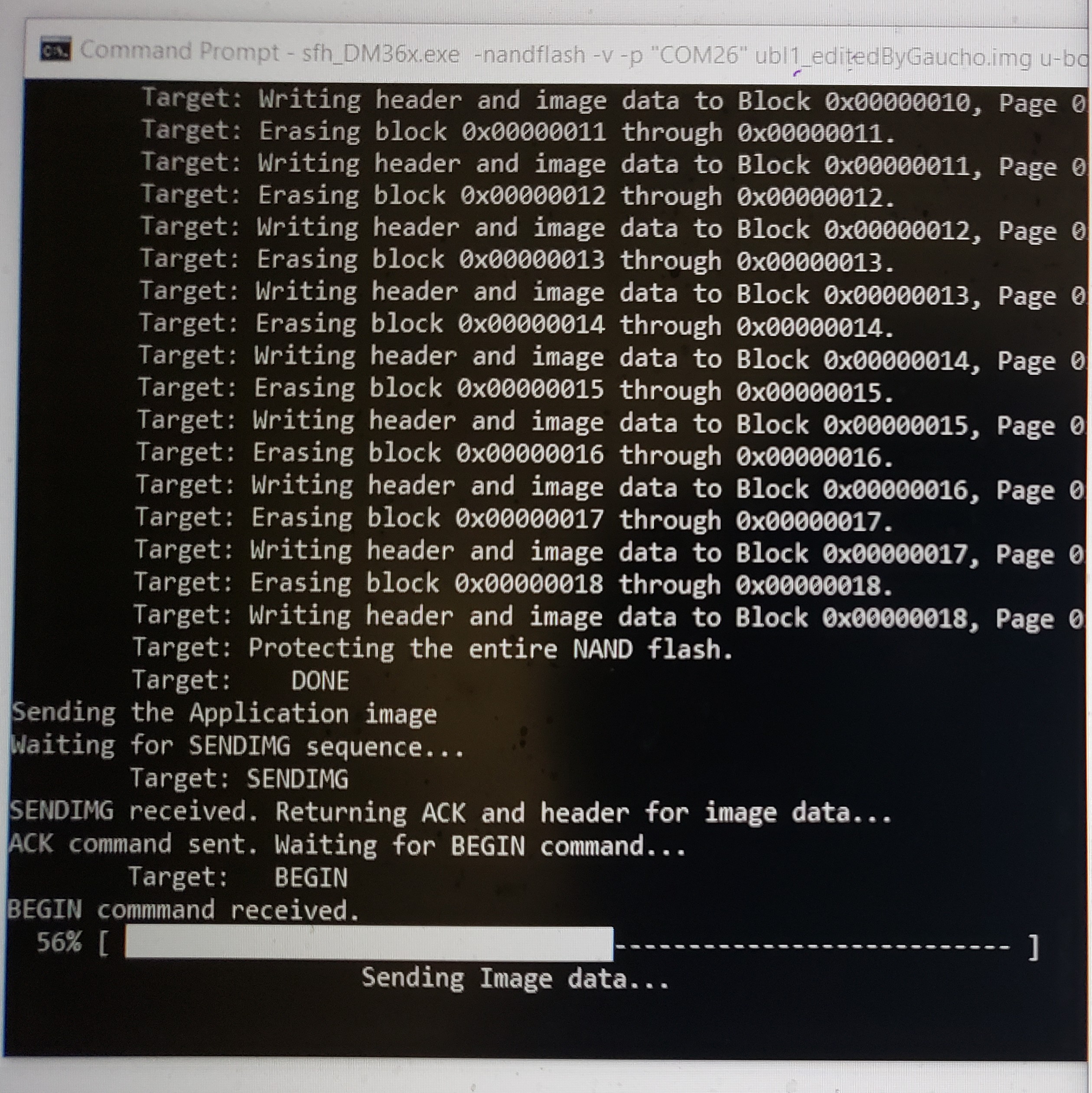
Pictured above is the inside of a DJI Phantom drone which I was working on. This unit had lost its live video feed. I was able to fix this unit by removing the rf board, soldering leads to the jtag connectors, and then re-flashing the firmware.
Builds: Mini-CNC Machine with GRBL Open Source Controller
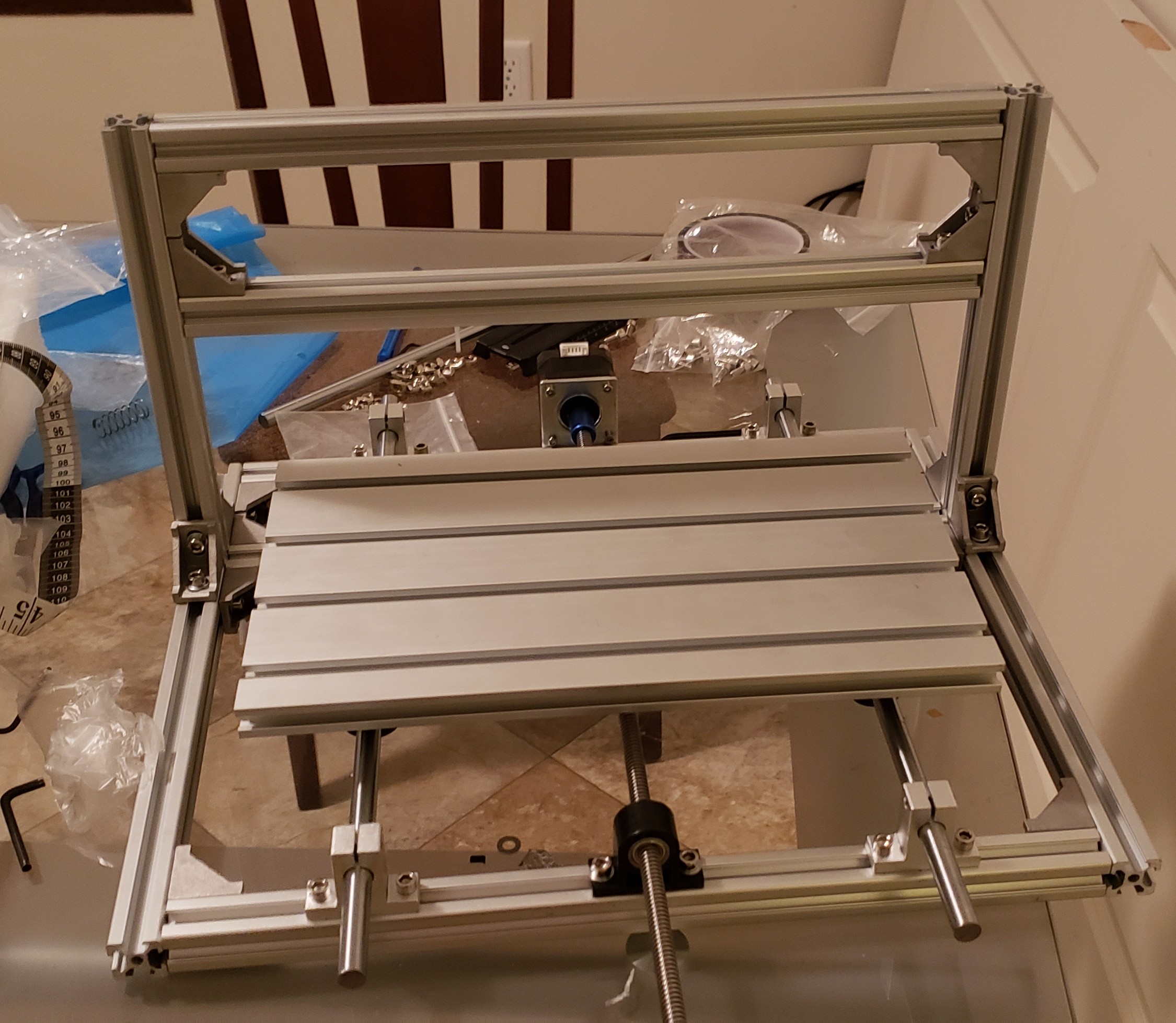
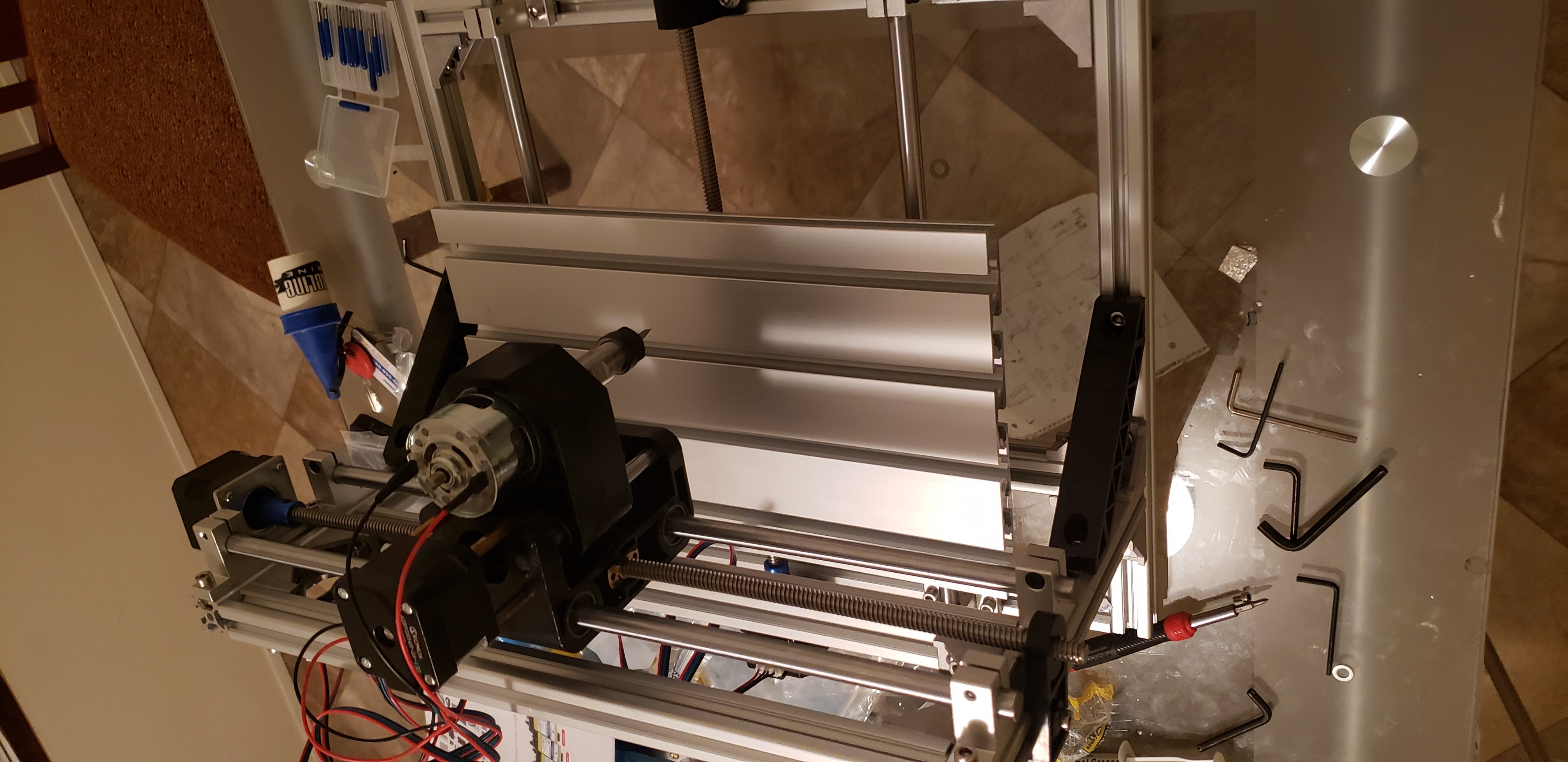
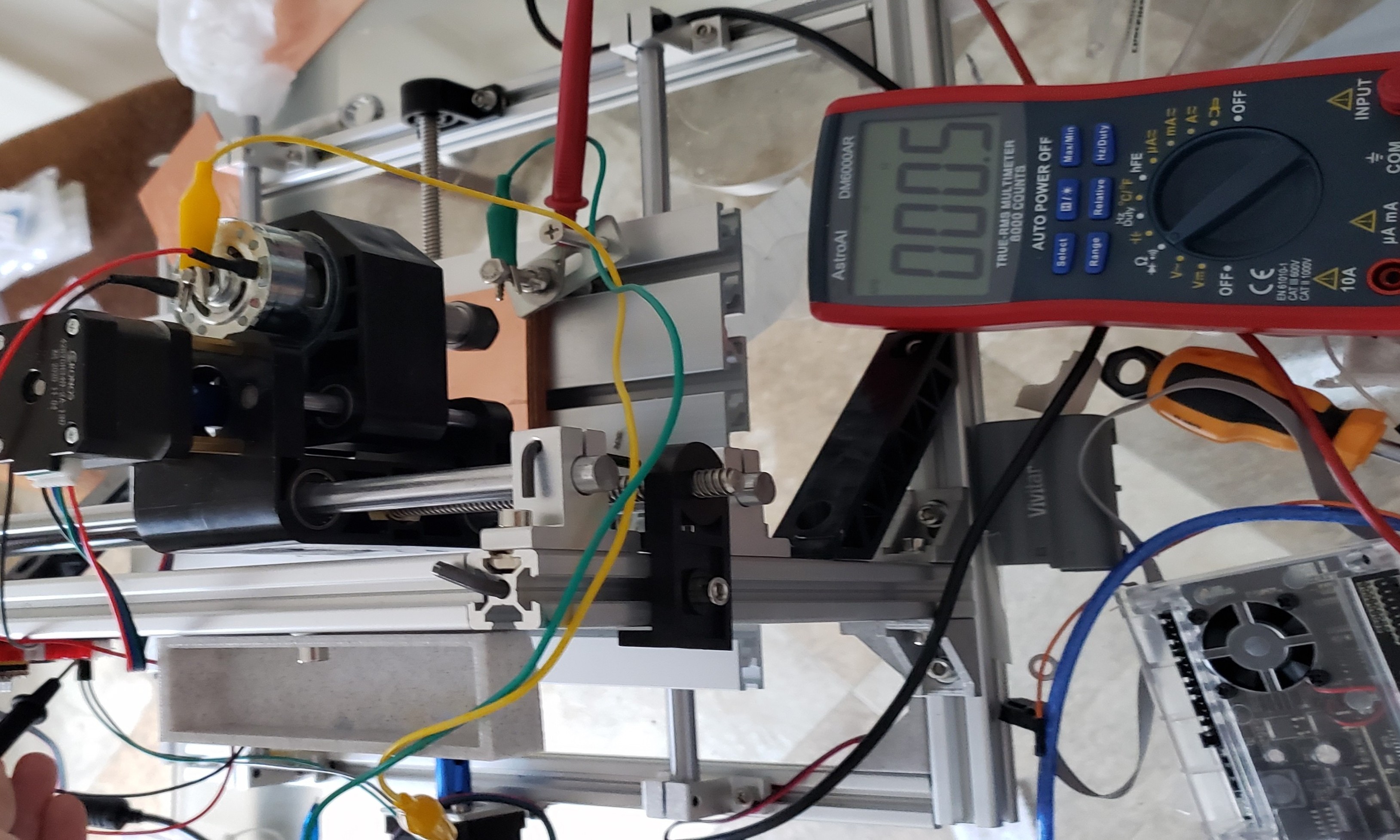
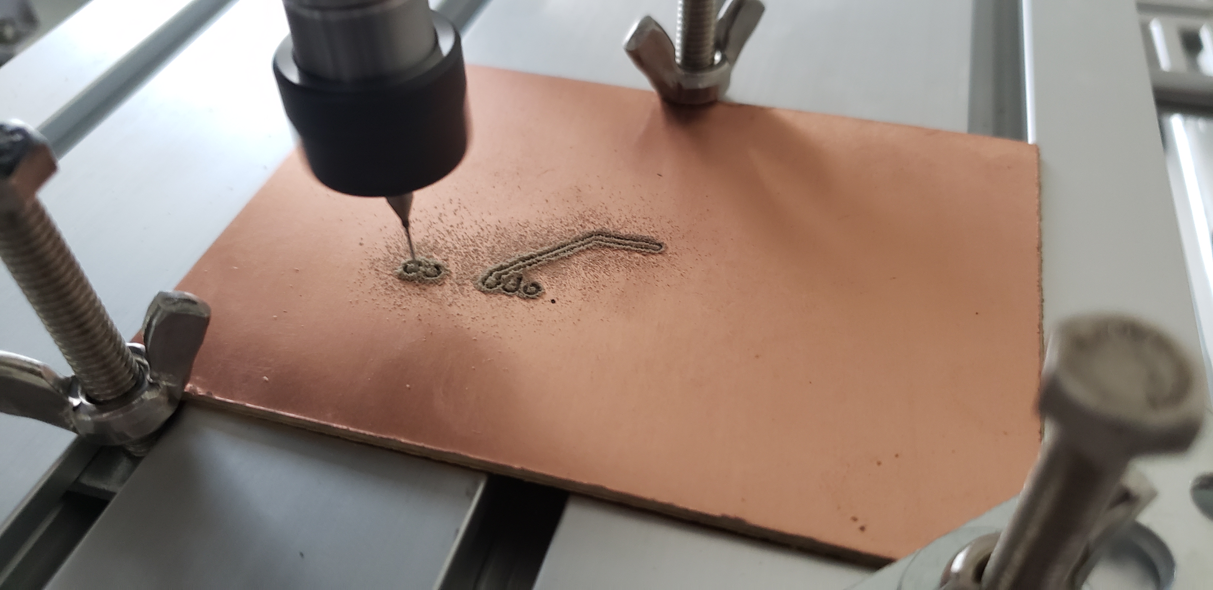
Pictured above is the mini-CNC I built using aluminum extrusion, stepper motors, a 10k rpm spindle motor, and an open-source GRBL control board. I was able to build the CNC for less than $200 total. My software workflow for milling PCBs was KiCAD (design the PCB, plot the GRBR files) --> FlatCAM (turn the GRBRs into a CAM file with the traces inverted --> bCNC (an open source CNC control software written in python. I tried various different software but this was my favorite as it had various options including an autolevel function (create heightmaps for even milling), simple GCode editing, and extensive customizability overall for various purposes.
GPS Speedometer for Boat/Bike
.jpg)
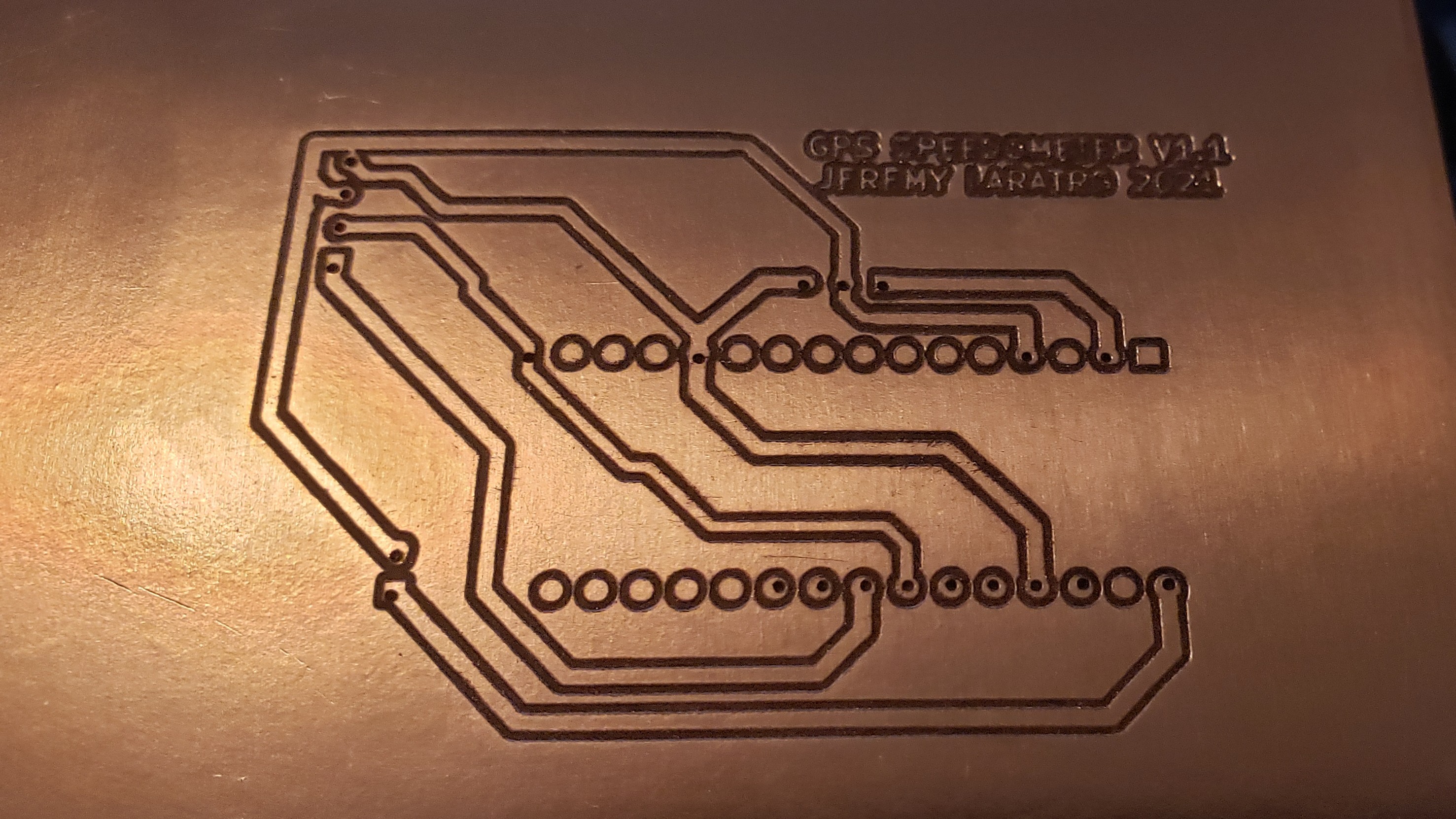
Pictured above are the first prototypes of a GPS speedometer I built. On the left, the upper side of a freshly-milled copper-clad PCB board, and to the right, a first-gen iteration using a breadboard. As usual, this project started with a problem I was facing -- I wanted a way to measure the speed of my small boat that I had recently purchased, but also wanted a portability aspect that I could potentially use for other modes of transportation, such as a bike. I also wanted to leave open the possibility of other future features, such as mapping. I decided on the following hardware:
Arduino Uno for initial prototypes, then I planned to migrate the ATMEGA328P as a standalone chip
NEO-6M GPS Module: This moodule fits all of my needs; it is cheap, small, and supported by existing Arduino libraries
OLED screen: I chose to use an OLED as I had a bunch of extras. They are also cheap and normally available.
A 3.3v LiON battery: Portable and cheap.
Class A Amp for Cell Phone
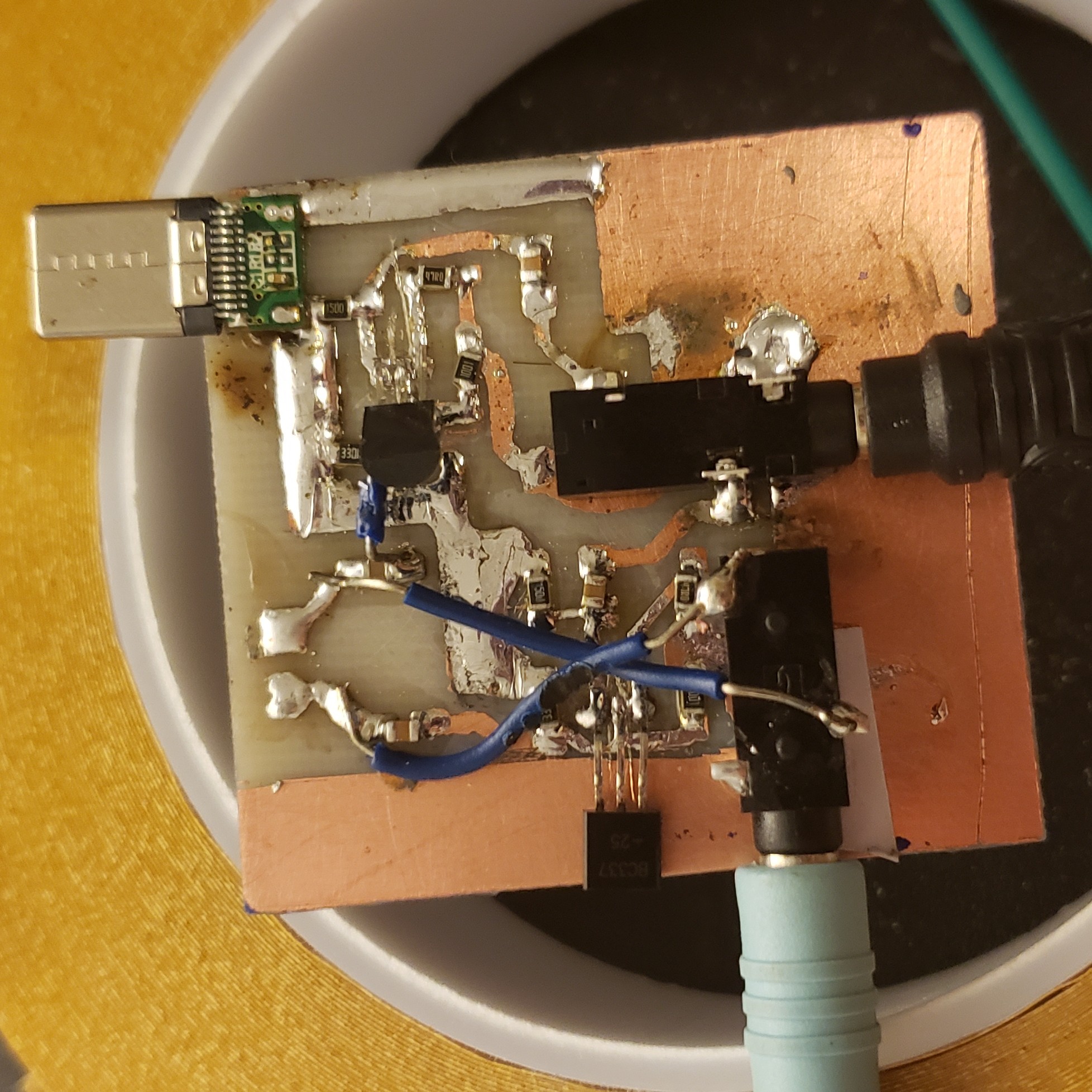
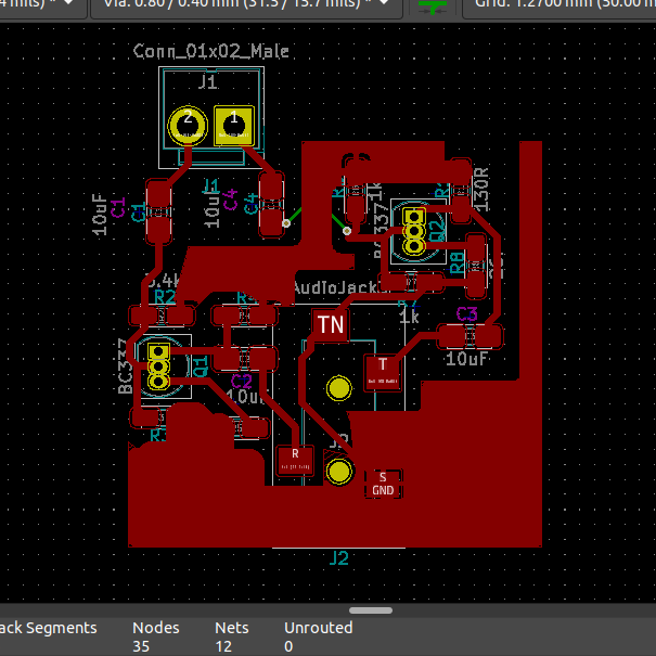
Pictured on the left is an early prototype created using a chemically etched copper-clad PCB board and SMT components which I soldered on. Pictured on the right is a prototype KiCAD PCB, which I can use to export GRBR files for professional fabrication from places like PCBWay or JLPCB, the two main services I use for fabrication. I started this project because I wanted to learn more about how audio circuits and amplifiers work. After coming across a video on Youtube by GreatScott Gadgets, I thought that this would be the perfect project to learn about amplifier circuits, practice my chemical etching process, and also create something fairly useful.
This circuit a simple Class A audio amplifier circuit. It attains power from the phone, so no external battery or power supply is needed, and uses an aux cord to receive the audio signals. It essentially works as a middle-man, where the audio output of the phone goes through the amplifier circuit, and then the amplified signal leave through the out-jack, into either headphones or a speaker. Class A amps are inherently inefficient, but it does produce a clean signal and noticeably louder output.
The hardware I used includes:
2x BC337 Transistors: These were perfect as they are cheap and I already had a bunch of them
SMT Ceramic Capacitors and SMT Think Film Resistors: I chose to use SMT components because I have a lot of them, and I also find them to be easier to work with, although many people disagree. I also wanted to confine the board to a single side as making two-sided designs does lengthen the process quite a bit when making home-made PCBs.
Standard Audio Jacks: I had quite a bit of left overs from the uSDX.
A USB-C Module: This circuit uses the phone's output for power, and I wanted to be able to plug it directly into my Note 9. This module is quite simple, as it is only for power, so none of the data lines need to be connected.
My Bench and Other Projects for Future Articles
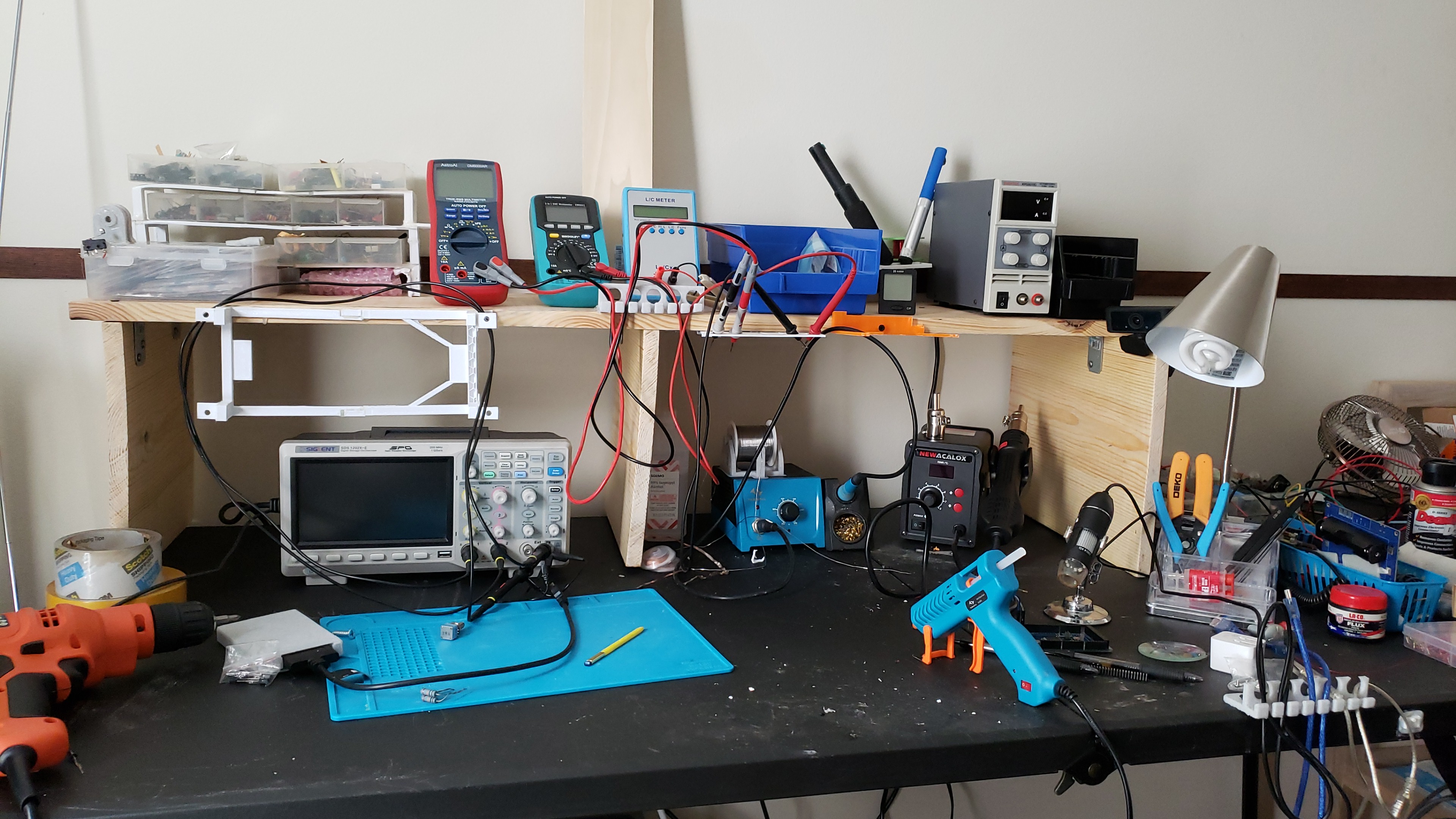
My Bench
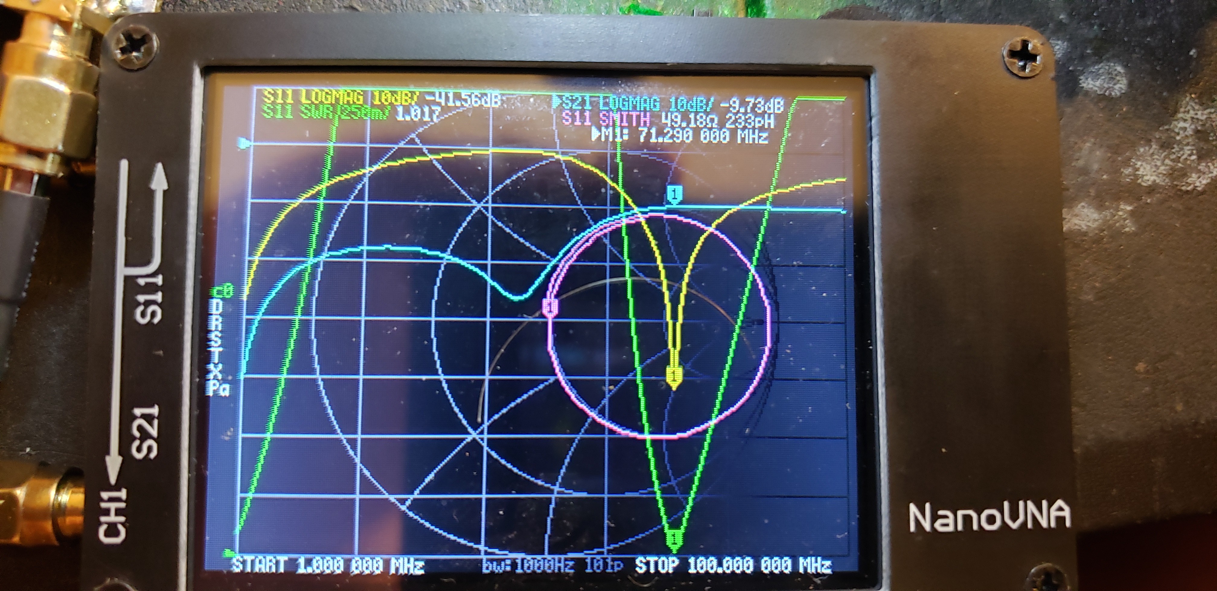
NanoVNA
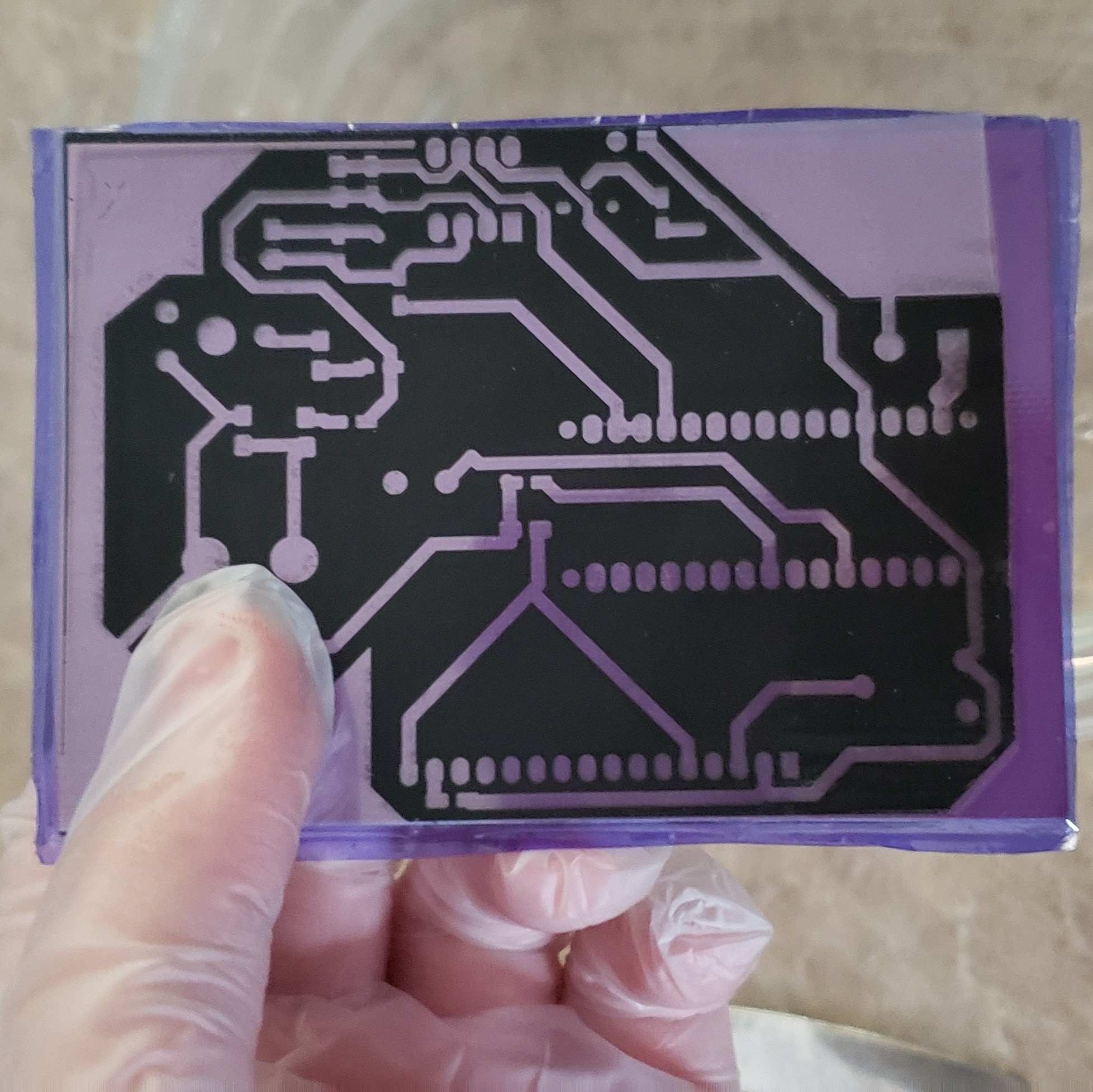
PCB with Photosensitive layer and stencil
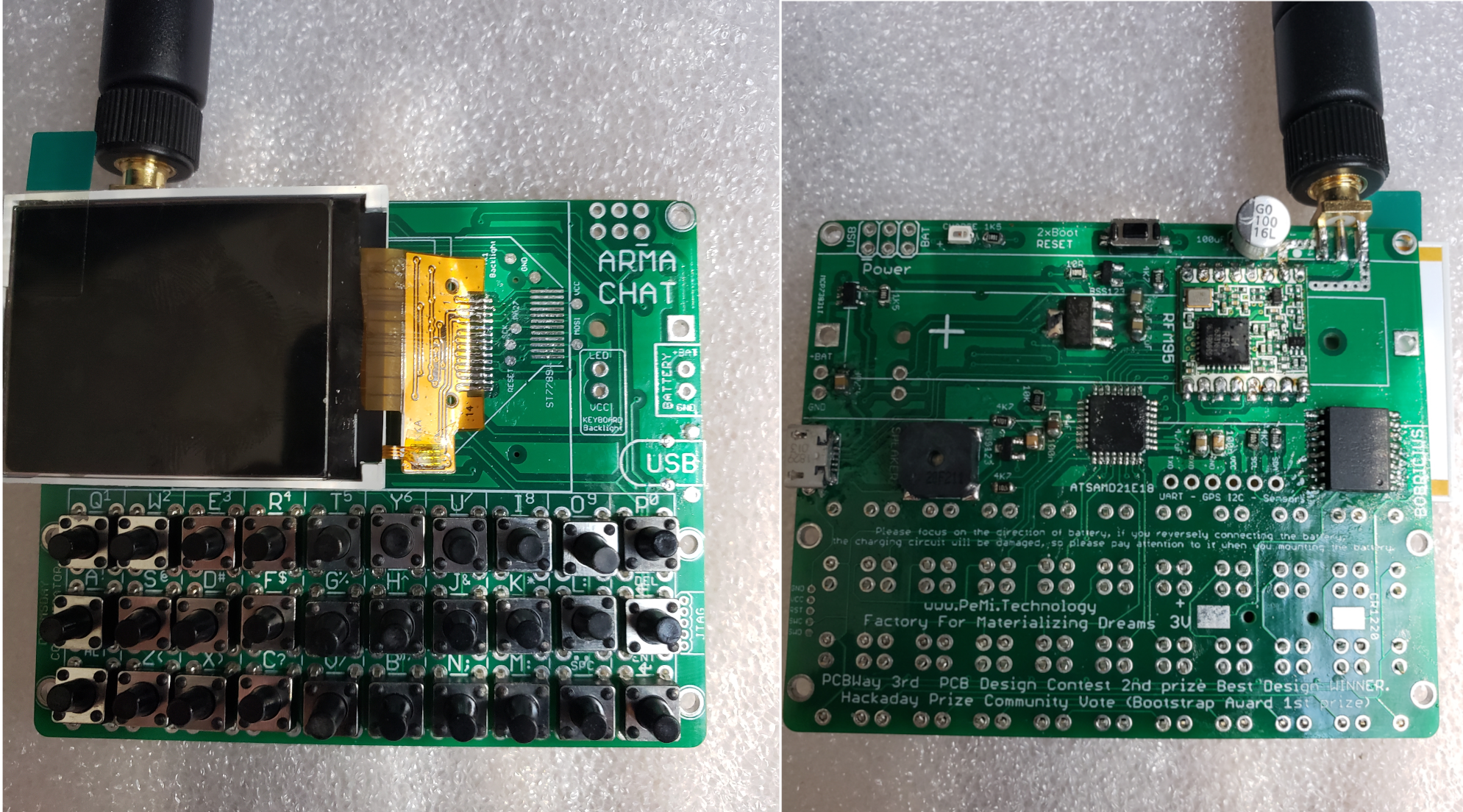
ArmaChat: A Standalone LoRa Text Messenger
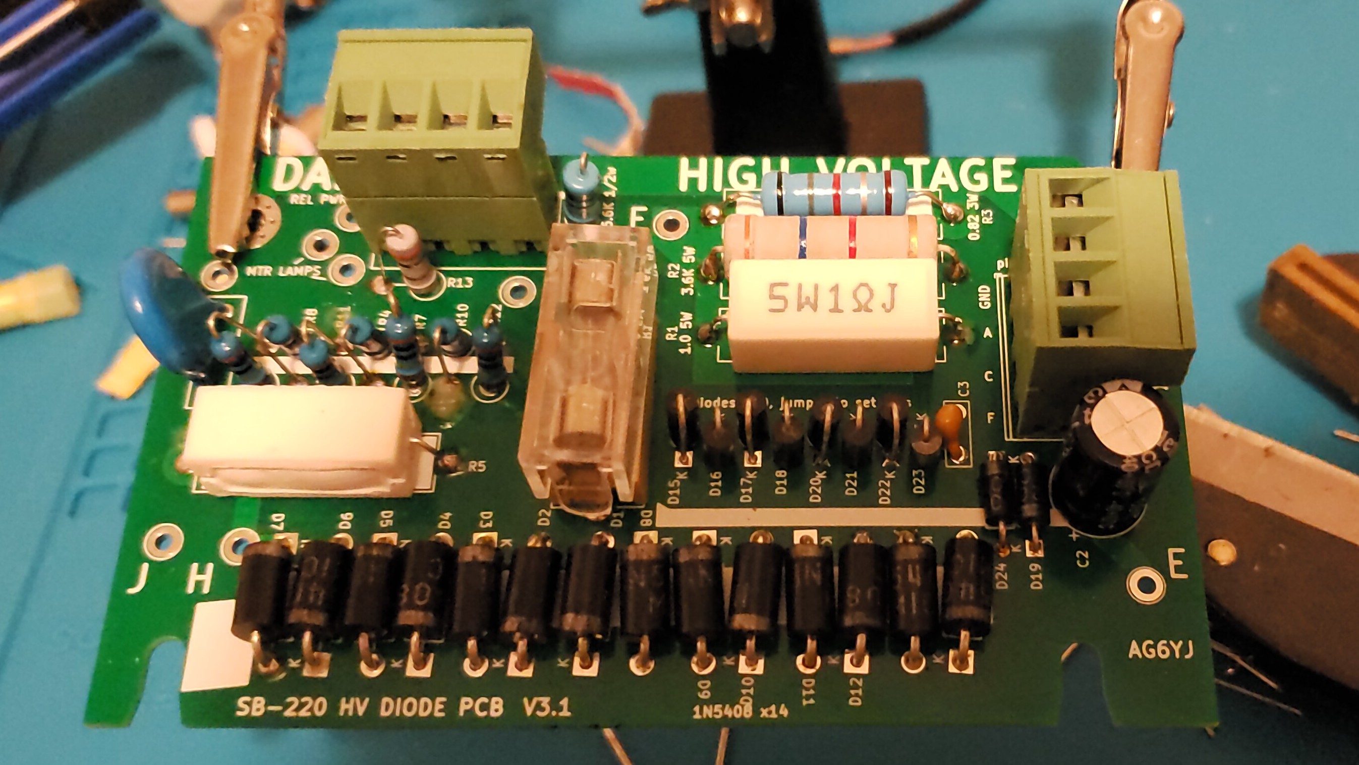
Heathkit 500w HF Amplifier Rebuild: High Voltage Board
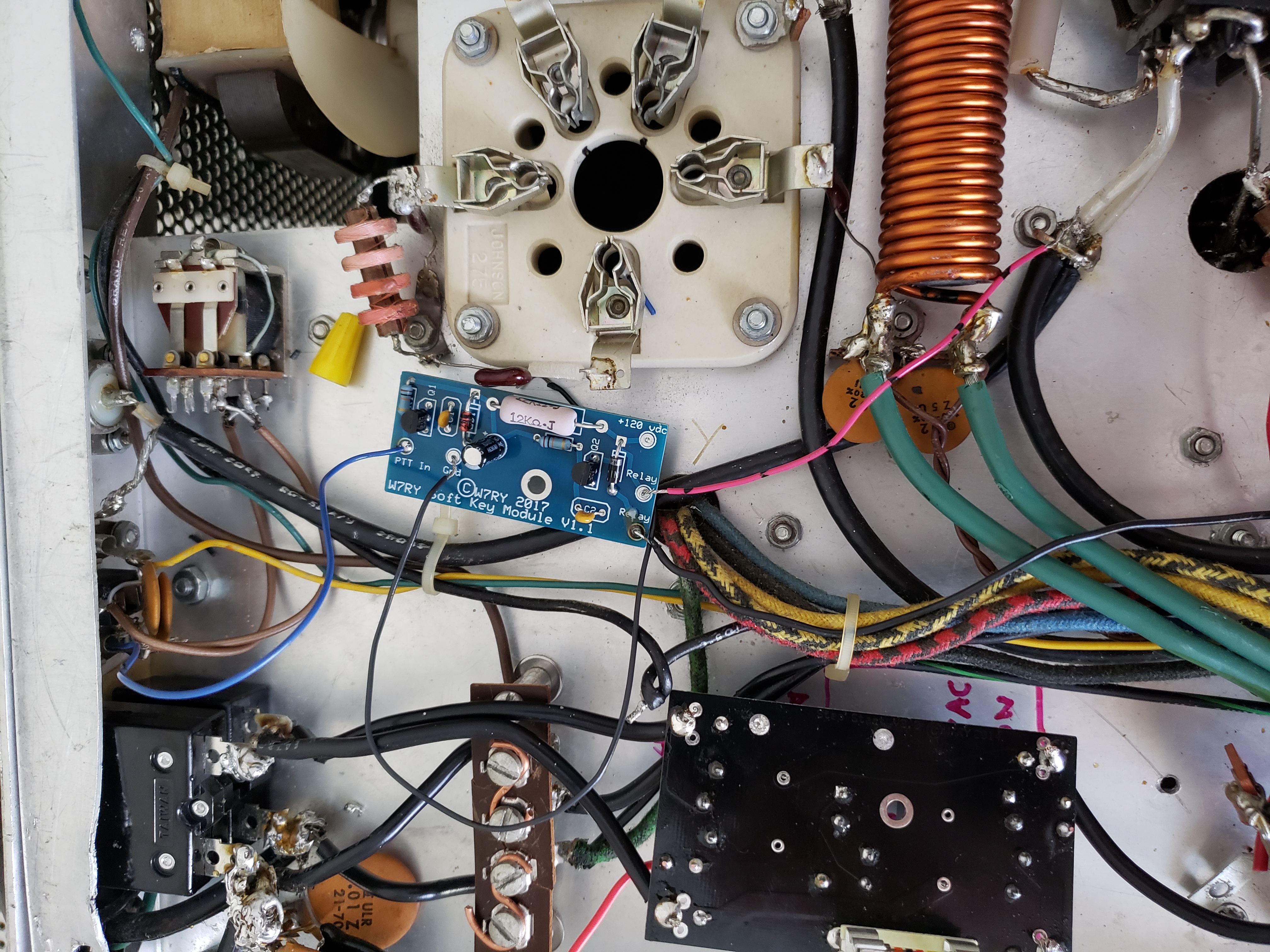
Heathkit 500w HF Amplifier Rebuild: Underside
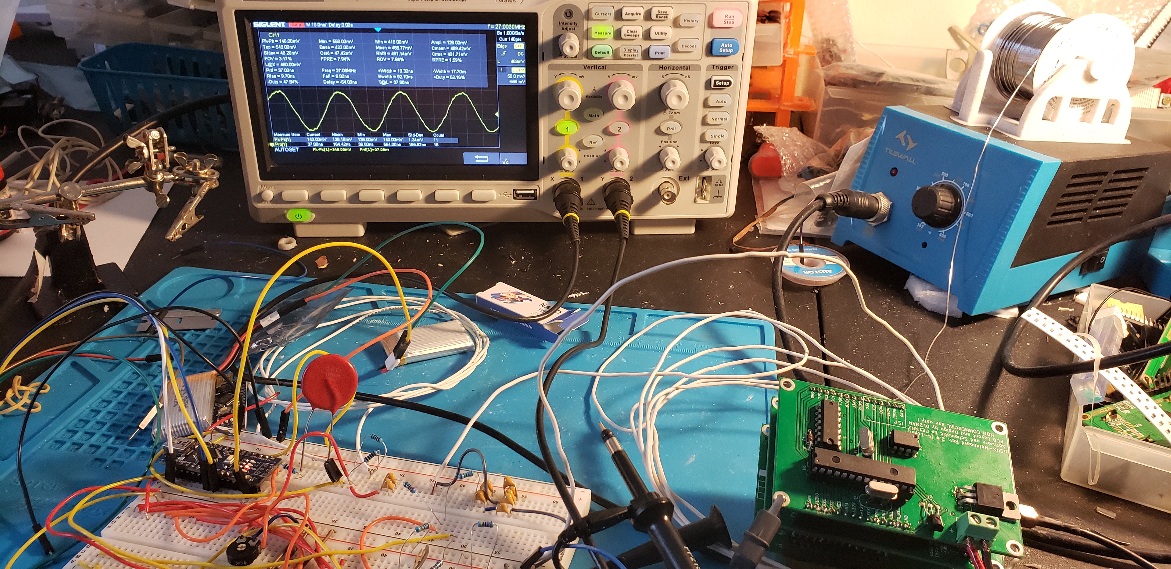
uSDX: Testing the Si5351